|
A Strobe Flasher For Night Cycling
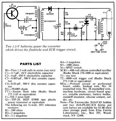
Uses a high-voltage xenon flash tube and dc/dc converter.
ALL BICYCLISTS and car drivers are aware of the need for visibility when riding a two-wheeler at night or in fog. However, providing a clear indication of a cyclist’s presence can be a real problem. Blinking incandescent lights can be used, but they put out only small amounts of light. The light described in this article uses a xenon tube to generate a bright flash that can be seen from a great distance—but is not intense enough to destroy a driver’s night vision. Simple circuitry al lows the project to be built at low cost, in a lightweight, compact package that can be secured to the bicycle or the rider’s belt. Principles of Operation. The light-producing element is a sealed glass tube containing two electrodes and filled with the inert gas, xenon. When a high voltage is applied to the tube, the gas ionizes. That is, some of the electrons are stripped from the xenon atoms. When the electrons and xenon ions recombine, the energy that caused them to separate is given up as light. If many atoms are ionized, the light output is intense.
Xenon flash lamps are usually operated in a pulsed mode. The intensity of their flashes gives good visibility, and their short duration keeps the average power applied to the tube low. However, the flash tubes require high voltages. In this circuit, a dc-to-dc converter supplies this high voltage, drawing power from two AA batteries. A capacitor stores charge which is needed for the large instantaneous flash current. To initiate ionization in the tube, a potential difference of about 4000 volts is required. This is developed by a trigger coil, or pulse transformer, which steps up the converter output.
About the Circuit.
Transistor Q1, transformer T1, and their associated components comprise an oscillator which is the heart of the dc-to-dc converter. When power is first applied, collector current builds up until the ferrite core of Ti saturates. At this point, base drive is removed from Q1, the transistor cuts off, and flux in the core decays. Then the cycle repeats itself again.
On the other side of T1, high voltage pulses developed across the secondary are rectified by D1, and charge C2 to +250 volts. The voltage divider composed of R2, R3, and R4 charges C3 to 90 volts and C4 to 200 volts. The time constants associated with these capacitors are small, so the voltages across C3 and C4 can be assumed to be proportional to that across C2.
When the potential across C3 reaches approximately 90 volts, neon lamp I1 fires and discharges C3 through the gate of SCR1. This causes SCR1 to turn on, and the charge stored in C4 is dumped into the primary of T2, the trigger coil. Because of T2’s high step-up ratio, this surge of current induces a potential difference of several thousand volts across the secondary. In turn, the flashtube fires, creating a bright flash of light as the charge stored in C2 flows through the tube. When C2’s charge is depleted, the tube stops conducting and goes dark. Then the rectified pulses from D1 start to charge up the capacitors, and the cycle begins again.
The flasher requires only two or three volts to function. Two penlight (AA) cells make a lightweight power source, but since current drain is 250 to 300 mA, carbon zinc cells should be used only if the flasher is intended as a back-up safety device in extreme circumstances. However, two alkaline AA cells should provide about six hours of intermittent operation. If the flasher is to be used frequently, rechargeable nickel-cadmium batteries should be installed. They will give about two hours use to a charge. (Of course, rechargeable or non-rechargeable C or D cells can be used if more extensive use in contemplated.
Construction.
The flasher can be built on a printed circuit or perforated board, and housed in any enclosure of sufficient size. The prototype was built in a small plastic box with a transparent top which protects the flash tube without obscuring its light output.
No matter which arrangement is chosen, the first step in constructing the flasher is to assemble T1. It is wound on a nylon bobbin that will be inserted into a two-piece ferrite pot core. Begin with the secondary. Allow a few inches of No. 34 enamelled wire to extend from a slot in the bobbin, and attach a ‘flag” of masking tape to the end of the wire. Mark the tape with an “S.” This will allow you to keep track of the start of the secondary winding, which is essential to proper phasing. Secure the wire to the bobbin with a piece of electrical tape, and then wind 350 turns, keeping each layer even. When you have finished, cover the winding with electrical tape, and leave a few inches of wire free to serve as a connecting lead for the “finish” end of the secondary.
The primary will be wound next, using No. 28 enamelled wire. Use a masking tape flag marked “P” to identify the start of the winding, and wind 16 turns in the same direction as you did for the secondary. When the primary is completely wound, cover it with a layer of electrical tape. As before, leave a few inches of wire free at both ends of the primary. Finally, wind the five-turn feedback winding in the same direction as the other two. Use No. 28 enamelled wire, identify the start of the winding with a tape flag marked “F,” and cover the completed bobbin with a layer of electrical tape. Again, leave a few inches of lead length on each side of the winding.
Insert the bobbin between the two pot core halves, and mount the trans former on the project board using #6-32 machine hardware. The ferrite core is very brittle, so the mounting hardware should be no more than finger tight. Use a daub of silicone cement to secure the nut to the board.
The flashtube should be mounted so that it can be seen and is somewhat protected from shock. The author mounted his flashtube on the circuit board using its leads and a standoff insulator. Note that the electrode composed of wire mesh is the cathode. Trigger transformer T2 should be positioned near the flashtube. The rest of the components can be mounted in any convenient manner. It is wise to leave the transformer leads long, as a mistake in the direction of a winding, or improperly identifying the start of a winding, will require a phasing change involving the reversal of one or more windings.
Checkout and Troubleshooting.
When you have completed building the project, double check all wiring, and then turn the unit on. The flashtube should flash about once each second, and an audible whistle should be heard near Ti as the dc-to dc converter oscillates.
If no whistle is heard, measure the battery voltage and current with a high-impedance multimeter. If no cur rent is being drawn from the battery, check the wiring to T1, Q1, R1, the battery, and switch S1. If current is being drawn, try reversing either the primary or feedback winding of T1, but not both!
The converter might oscillate but the flashtube won’t flash. In that case, measure the voltage across C2. Al though current is limited, the capacitor’s voltage can give you an unpleasant shock, so be careful! A reading of 250 to 300 volts is normal. But if the voltage is below this level, disconnect R2 and the anode of FT1 from the positive plate of C2. If the voltage is now correct, the problem is located in the trigger circuit for the flashtube. If the voltage is low but not zero, try reversing the secondary winding of T1. Zero voltage points to incorrect wiring or a defective D1 or C2 component.
When the voltage across C2 is correct but there is no flash, the trigger circuit must be examined. Measure the voltage between the anode and cathode of SCR1. You should obtain a reading of 200 volts or so. If you do, short these two points with a jumper. The tube should flash as you do this. If it doesn’t, either it or the trigger coil is defective. Other possibilities are a faulty SCR or trigger component (I1. etc.) or incorrect wiring of that part of the circuit that generates the trigger.
Final Thoughts.
If desired, small leather straps can be secured to the flasher enclosure to serve as belt loops. The unit is small enough to be mounted either on the bicycle or on the cyclist’s arm or leg. It can also be taken along for hikes on dark country roads. You will probably find many other applications for this handy little bicycle flasher.
|
 Most of the components can be
obtained from any electronic parts store, including flash tube FT1
and trigger coil T2. However, the converter transformer Ti must be
wound on a Ferrox cube 261 6-F1D bobbin and uses two Ferrox cube 261
6-PLOO-3C8 pot core halves. These parts are available from some
industrial distributors, and a mail-order source is included in the
parts list.
Most of the components can be
obtained from any electronic parts store, including flash tube FT1
and trigger coil T2. However, the converter transformer Ti must be
wound on a Ferrox cube 261 6-F1D bobbin and uses two Ferrox cube 261
6-PLOO-3C8 pot core halves. These parts are available from some
industrial distributors, and a mail-order source is included in the
parts list.Copyright by Bill Bytheway, K7TTY February 2012