|
AN APPLIANCE “OFF” REMINDER
A low-cost project provides an audible alert when an appliance indicator light goes off.
IT IS often useful, sometimes vital, for the user of an appliance to know if and when it ceases to operate, whether by design or due to a power failure. Usually, this is not difficult to accomplish, since most appliances are equipped with indicator lights that show when they are working. But if the appliance is not in direct view, keeping track of it can be a great annoyance.
One solution to this problem is to use an electronic “eye” that senses the radiation from the indicator light and sounds an alarm when it is interrupted. For convenience, only the sensor is required to be physically at the monitoring point; the alarm can be located where it is easily heard.
The Lights-Out Alert described here provides the answer. It is battery powered and reliable; can be built from low cost components; and is usable with al most any sort of power-on light indicator.
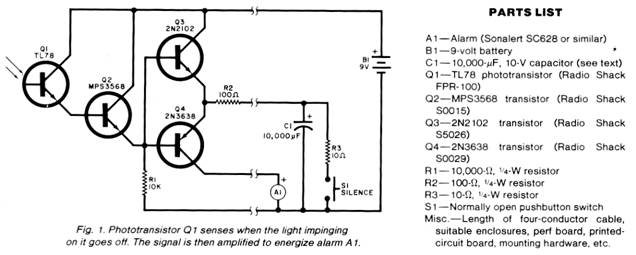
Circuit Operation. As shown in Fig1, phototransistor QI and Darlington connected Q2 form a high-gain optical to electrical transducer that drives a charge pump made up of Q3 and Q4 and associated components:
When no light strikes Q1, its resistance should be high enough so that Q2 is Cut off. Any slight leakage from Q2 should produce less than 0.7 volt across R1—not enough to turn on Q3. Assuming that capacitor C1 has been discharged by the operation of S1, Q4 also lacks the voltage required to turn it on. Thus, all four transistors are off and current from the battery is almost nil.
When light strikes Q1, its resistance drops, depending on the illumination level, and Q2 is turned on. The voltage developed across RI turns Q3 on provided C1 is discharged. Thus Q4 is driven deeper into cutoff. Current flows through Q3 and R2 to charge C1. When the voltage across C1 rises to within 0.7 volt of that across R1, Q3 is cut off. This condition will last as long as transistor Q1 is illuminated.
When the illumination ceases, the voltage across R1 drops. Since C1 is charged high enough to reverse-bias Q3, this transistor cuts off and turns on Q4. Discharge current from C1 now flows through R2 and Q4 to drive alarm A1.
After some time (about one minute per 10,000 microfarads of C1), C1 becomes discharged and the alarm turns off. The circuit is then ready for the next illumination period, with no current drawn from B). Switch S1, in conjunction with R3, provides manual silencing of the alarm. This switch should not be operated during the charging cycle of C1 because this will tend to deplete the battery’s charge.
Construction. The circuit consists of two physically independent sections — the light-sensitive portion and the alarm/power package, with the two interconnected by a length of flexible four-conductor cable.
The four transistors and two resistors that form the photosensor can be assembled on a small piece of perforated board or a small printed-circuit board. Make sure that the sensitive face of Q1 is in the clear so that light can pass through a hole in the case and shine on this surface. Select a low-leakage device for Q2. If phototransistor Q1 is a low-gain device (units vary with manufacturer), increase the value of R1. However, to avoid false alarms do not make the circuit too sensitive.
The board can be mounted in a small enclosure having a hole drilled so that external light can fall on the sensitive face of Q1. Another small hole can be used for the four-conductor cable. The alarm/power elements are mounted in a separate enclosure with holes near the alarm so that it can be heard.
To test the project, expose the photo sensitive surface of Q1 to an ordinary household light bulb at a distance of about 18 inches. When the light source is removed, the alarm should sound for approximately one minute. Changing the value of C1 changes the alarm-on time. The alarm can be silenced by operating switch S1.
|
Copyright by Bill Bytheway, K7TTY February 2012