|
Aids for the Blind
Probably the simplest gadget you can build for a blind friend or relative is a light probe that produces a sound when a photodetector is illuminated. Light probes date from 1912 when British scientist Fournier d’Albe built a device he called the “Exploring Octophone.” It employed a selenium cell in a Wheatstone bridge and generated a musical tone as light intensity was varied.
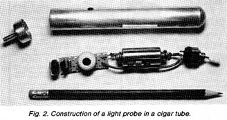
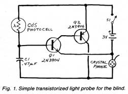
You can build an updated version of d’Albe’s light probe(Fig. 1). This circuit, which I described in a previous article(“Build a Light Probe,” POPULAR ELECTRONICS, March 1973, pp. 42-43), can be easily installed in an aluminum or plastic cigar tube (Fig. 2).
The circuit is a two-transistor regenerative amplifier. Its frequency of oscillation depends on the amount of light striking the sensitive surface of the cadmium-sulfide photocell.
Audio output is supplied by a crystal earphone that serves as a miniature speaker. The volume is sufficiently high so that the user can hear the tone, but it is not so loud as to distract nearby persons.
The probe can be made much smaller than the unit shown in Fig. 2. Several years ago, I built a probe, complete with mercury button cell and hearing-aid receiver, into a small plastic tube measuring about 3/8" x 1”. This was made possible by the tiny but surprisingly effective hearing-aid receiver unit I used in its construction. I intended to attach the probe to a key chain but, because of its small size, I promptly misplaced it.
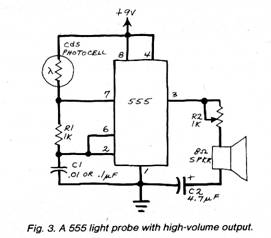
There are many ways to make circuits which produce a tone whose frequency is dependent upon light. Figure 3, for example, is an IC version designed around the readily avail able, inexpensive 555 timer. This circuit is very sensitive and can be adjusted to provide various frequency ranges and threshold levels, but it consumes more current than the circuit shown in Fig. 1.
An important advantage of the circuit in Fig. 3 is that it can provide more drive current to a small speaker or other transducer than the transistor Circuit. This may prove a significant advantage to blind people with a hearing problem, a not uncommon combination among older individuals.
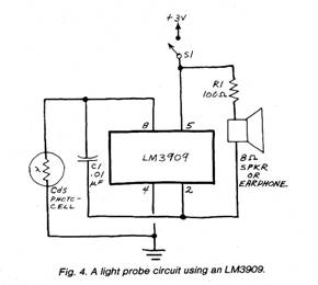
Still another light probe circuit is shown in Fig. 4. This circuit uses the amazingly versatile LM3909 LED flasher chip as a light-controlled audio oscillator.
Light probes have many practical applications. Blind telephone operators have used them to find illuminated indicator lights on a switchboard. Such probes can also be used to deter mine if room lights are on or off, whether or not appliances with pilot lights are on, and to find color changes on clothing and wall surfaces.
Another simple but very useful aid for blind people is a liquid-level indicator. A blind person usually determines when a cup or glass has been filled by keeping a finger tip inside the rim of the container while pouring the liquid. This procedure can be uncomfortable if the beverage is hot and can be unseemly if sighted guests are being served.
The “Project of the Month” in this issue describes a very simple two-tone liquid-level indicator which is essentially identical to the light probe in Fig. 4. Indeed, you may wish to build an LM3909 oscillator with a phone-jack input port. You can then connect either the liquid-level probes described in the “Project of the Month” or the photocell as in Fig. 4.
Partial or even total loss of vision can be an unfortunate side effect of advanced diabetes. A modification of the light probe concept can be used to help blind diabetics perform their own tests of the sugar level in their urine.
Urinary sugar content is ordinarily determined by dipping a strip of test paper into a specimen. Color changes in the paper denote the sugar level. You can detect the color of a test strip by making a light-tight chamber fitted with a cadmiumsulfide photocell and a small lamp. When a test strip is placed in the chamber, the resistance of the photocell will be determined by the color of the strip.
I built a urine-monitoring device similar to this in 1966, and at least one such device is commercially available today. If you want to assemble one for a blind diabetic, spend the time to calibrate it carefully. Make sure the unit can be reliably operated by a blind person. Erroneous readings from the unit could prove extremely hazardous to a person who uses it.
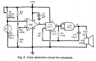
To experiment along these lines, Fig. 5 is the schematic of an elementary circuit with which you can get started. The operational amplifier, operated without a feedback resistor so that it functions as a comparator, has its switching threshold determined by the setting of R3. The photocell is one section of a voltage divider. When the divider output reaches the switching threshold set by R3, the comparator actuates the tone generator made from two of the gates in a 4011.
In using this circuit, the photocell is pointed at an illuminated test strip (you can obtain test paper at a pharmacy). The output of the divider is a voltage representative of the reflectance of the strip. Potentiometer R3 is then adjusted until the tone is heard. Raised markings at predetermined points form a scale for the control knob, which should have a stubby pointer, that a blind person could “read” easily.
Aids for the Deaf. We’ve already discussed the repair of hearing aids. In a pinch, you can actually make a usable hearing aid from a miniature audio-amplifier circuit or a low-cost portable, commercial amplifier and a microphone and earphone. This assembly will be much bulkier than an ordinary hearing aid, and it will pick up rustling clothing noises unless the microphone is mounted in an unobstructed location. It will also be much more subject to acoustic feedback and oscillation, which can be frightening. Such an aid will not necessarily be as good for the amplification of audio frequencies as are the specialized designs of most hearing aids. Nevertheless, it can prove very helpful in an emergency or when a person’s hearing aid is being repaired.
The totally deaf cannot be helped by conventional hearing aids. Ways to signal such people include a light panel, CRT display, or printer.
A simple yes-no signaling system can be made with a tactile stimulator. Such devices can be made from piezoelectric substances which, when electrically stimulated, vibrate or poke against the surface of the skin. A more homely but simpler approach that rarely fails to get a person’s attention is an eccentric weight attached to the shaft of a small dc motor. When the motor spins, the vibrations generated by the offset weight is easily felt.
|
Copyright by Bill Bytheway, K7TTY February 2012