|
THE “BUCKET BRIGADE” AUDIO DELAY LINE Allows user to simulate larger listening room.
Also used by recordists and musicians for
special sound effects
THE SOUND of recorded music being played is a listening experience that changes according to the room you are in. If the room is too “live” or too “dead”, the sound appears to be unnatural. When the room has an ultra-modern decor and lots of glass window areas, the effect on the music is “bouncey.” With heavy drapes, carpeting, and thickly padded furniture, plus a minimum of hard surfaces, the effect approaches that of an anechoic chamber—with very little sound reflection.
For the latter, you can either throw away your sofa pillows and pull down the drapes, or you can add a time delay device to your audio system to create a more natural ambience. Since you may not care to redecorate, you can create an echo (audio signal time delay) and reverberation (later reflections) and achieve a livelier sound.
Until recently, the only means of obtaining an audio signal delay has been through the use of very expensive electronic equipment. Now there is a new type of IC — the “bucket brigade” — and you can build your own delay system for as little as $39 in mono and $59 in stereo. Connected between source and preamp or preamp and power amplifier (at the tape monitoring jacks possibly), it provides an adjustable, signal echo that can enhance the sound in most home listening rooms. With minor connection changes, it also can be used as a phasor / flanger, giving you a sound effect for tape recording purposes and electric-guitar playing used by the professionals.
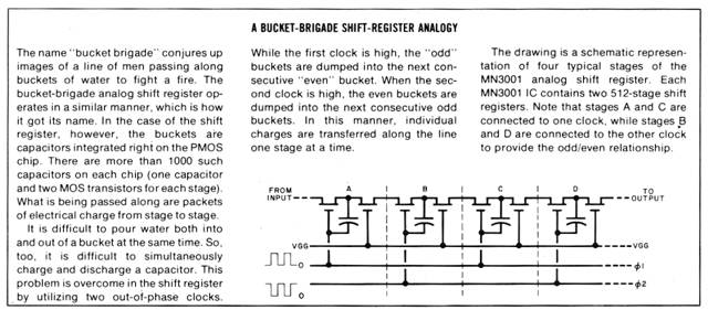
The bucket-brigade IC is a MOS type shift register that contains two 512-stage registers in a single 14-pin package. When an audio signal is applied to the input of the bucket brigade and a clock generator drives the IC, the signal is stepped along stage by stage until it comes out delayed a discrete interval in time. By adding this delayed signal to the original, reverberation is simulated.
In addition to providing real-time ambience, the bucket-brigade circuit can be used with a tape recorder to provide simulated stereo sound from mono sources, a means for “double voicing,” and “phasor / flanging.”
Technical Details.
If you can delay an audio signal, you can create a number of useful sound effects. The most obvious is simulating echo, though delays provided by the bucket brigade are too short to be discerned as discrete echoes. Recirculating the delayed signal at reduced gain can approximate the natural decay of echoes in a reverberant room. By adding some gain during the recirculation of the delayed signal, you can create an unnatural “door-spring” effect on the music.
Delay an instrument or voice track by 30 or 40 ms and add the delayed signal back to the original signal, and you will make the output sound fuller and give it the effect of more than the original number of voices or instruments. This commonly used technique is known as “double voicing.”
Another popular short-delay effect is a strange sound that results from a technique known as “phasing” or “reel flanging.” The name is derived from its original implementation where a tape recorder was used to create the time delay and the friction of a well-placed hand on the outside edge of the tape-feed reel varied the delay to produce the acoustic effect. This effect can be created totally by electronic means by delaying the signal 0.5 to 5 ms while adding or subtracting the delayed signal from the original signal.
The phasor/flanger mode can be used to simulate stereophonic sound from a monophonic source. To do this, the phased output derived by adding the delayed signal goes to one channel, while the output derived by subtracting the delayed signal goes to the other. To the listener, the phasing effect cancels leaving a reasonable pseudo-stereo effect.
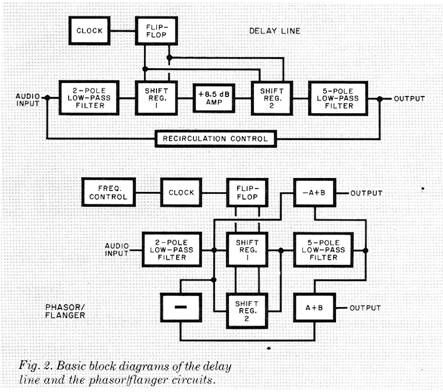
The basic block diagrams of the delay-line and phasor/flanger circuits are shown in Fig. 2. The hearts of the circuits, of course, are the bucket brigade IC’s, which can directly process analog signals. The circuits do not require costly analog-to-digital and digital-to-analog converters. When the clock pulse from the flip flop is applied to the bucket-brigade IC, the dc voltage present at the input is shifted into the register. The discrete bits are transferred stage by stage with successive clock pulses until, after 256 pulses, they reach the end of the line and provide the output.
The output waveform is smoothed by a low-pass filter and duplicates whatever signal was present at the input but delayed in time by 256 times the period of the clock frequency. (Period is equal to the reciprocal of the frequency.) For example, If the clock frequency is 100,000 Hz, the delay would be 256 x 1/100,000 = 2.56 ms.
In the delay mode, the two shift registers are connected in series, which allows twice the clock frequency to be used. Therefore, twice the bandwidth of a single shift register can be programmed for the same time delay. Even in this double-bandwidth mode, the clock frequency required for a 40-ms delay limits the bandwidth to a maximum input signal frequency of 3750 Hz, which is adequate for voice but less than adequate for many musical instruments. In most applications where the delayed signal is added to the original signal, the reduction in bandwidth will be masked by the high-frequency signals present in the original. To compensate for normal signal attenuation, an 8.5-dB amplifier is used between the shift registers.
How It Works.
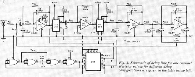
The schematic diagrams of the delay-line and phasor / flanger configurations of the circuit are shown in Fig. 3 and Fig. 4, respectively. In both cases, quad NOR gate IC4 is wired as an astable multivibrator operating at twice the desired clock rate’s frequency. The output of IC4 goes to flip-flop IC5, which provides a pair of complementary (180° out of phase with each other) output clock pulses with 50% duty cycles. These pulses then “clock” the shift registers in IC2. Frequency determining resistor R16 is fixed in the delay configuration, while resistance can be added via a pair of connectors to change the clock frequency in the phasor/flanger.
The audio input signal is conditioned by seven poles of low-pass filtering in which IC3 and half of IC1 are used. The filters provide a total of 42-dB/octave attenuation above the tuning frequency. For example, if the filter were tuned for 5000 Hz, a 10,000-Hz signal would be attenuated by more than 100:1.
When filters are designed with high-gain operational amplifiers (op amps), it is possible to have their out puts increase before rolling off at the rate of 6 dB/octave per pole. Such filters are termed “under damped.” By carefully selecting the proper balance of under-damped and over-damped (RC) filter sections, it is possible to design a filter that is flat in the desired passband so that it is 3dB down at the tuning frequency and has a roll-off rate of 6 dB times the number of poles.
This is what has been done in the delay-line and phasor/flanger circuits.
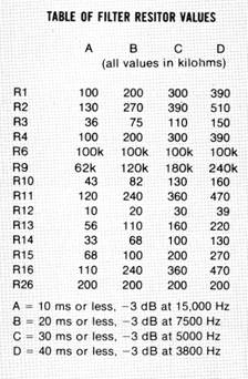
Quite a bit of mathematical computation is normally required to determine the values of the filter resistors to use. To simplify matters, you can select the appropriate resistor values from the Table of Filter Resistor Values. Use this Table for selecting resistor values for only the delay-line circuit. (The filter resistor values specified in Fig. 4 and its accompanying Parts List will provide an optimized 5-ms delay, with the output 3dB down at 15,000 Hz for the phasor/flanger.)
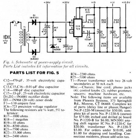
The power supply is shown in Fig. 5. It uses a voltage regulator, IC6, to generate the main 15-volt supply output. The shift register requires supplies of both +1 and + 20 volts. The +20-volt line is obtained through the use of zener diode D3, while the +1 volt line is derived from the voltage divider consisting of R22 and R23. Since the op amps are being operated from a single-ended supply, it is necessary to have the 10.5-volt supply line serve as the reference point in the circuit for these IC’s.
Construction.
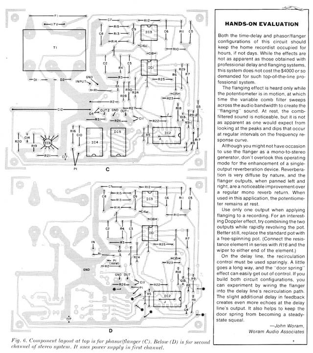
The actual-size etching and drilling guide, the same for both circuit configurations but wired differently as required, is shown in Fig.6A. The parts-placement guides for the delay-line and phasor/flanger configurations are shown in Figs. 6B and 6C, respectively.
Before installing any components on the board, mount and solder into place the wire jumpers. Then, wire the board as in Fig. 6B or Fig. 6C, depending on the desired mode of operation. Be careful to properly orient all semiconductor devices and electrolytic capacitors. Be sure to handle the MOS devices with care to prevent them from being damaged by static charges. You can mount the IC’s directly on the board or use sockets. Use a low-power soldering iron (25 to 35 watts) and fine solder, and watch out for solder bridges between the closely spaced pads on the board.
The wiring guide for the second pc board for a delay line for stereo is shown in Fig. 6D. Note that the power supply section is not repeated; you get power and clock pulses from the first board via wire interconnections.
Solder lengths of hookup wire to the pads that are to interconnect with the off-the-board pots and jacks. Then drill holes for the line cord, jacks, pots, and board mounting in a 5” x 4” x 3” (12.7 x 10.1 x 7.6 cm) aluminum chassis box. Locate the line cord and jack holes on a wall directly opposite the wall through which the pot holes have been drilled.
Use machine hardware and spacers to mount the pc board assembly to the floor of the aluminum box. If you are assembling a stereo delay line mount the second board assembly over the first with short spacers and machine hardware after interconnecting the power-supply and clock-drive lines with hookup wire. (Be sure to make the interconnections before fastening the boards together.) Connect and solder the free ends of the hookup wires from the board(s) to the appropriate lugs in the jacks and pots.
HANDS-ON EVALUATION
Both the time-delay and phasor/flanger configurations of this circuit should keep the home recordist occupied for hours, if not days. While the effects are not as apparent as those obtained with professional delay and flanging systems, this system does not cost the $4000 or so demanded for such top-of-the-line professional system.
The flanging effect is heard only while the potentiometer is in motion, at which time the variable comb filter sweeps across the audio bandwidth to create the “flanging” sound. At rest, the comb filtered sound is noticeable, but it is not as apparent as one would expect from looking at the peaks and dips that occur at regular intervals on the frequency response curve.
Although you might not have occasion to use the flanger as a mono-to-stereo generator, don’t overlook this operating mode for the enhancement of a single output reverberation device. Reverberation is very diffuse by nature, and the flanger outputs, when panned left and right, are a noticeable improvement over a regular mono reverb return. When used in this application, the potentiometer remains at rest.
Use only one output when applying flanging to a recording. For an interesting Doppler effect, try combining the two outputs while rapidly revolving the pot. Better still, replace the standard pot with a free-spinning pot. (Connect the resistance element in series with R16 and the wiper to either end of the element.)
On the delay line, the recirculation control must be used sparingly. A little goes a long way, and the “door spring” effect can easily get out of control. If you build both circuit configurations, you can experiment by wiring the flanger into the delay line’s recirculation path. The slight additional delay in feedback creates even more echoes at the delay line’s output. It also helps to keep the door spring from becoming a steady state squeal.
John Woram, Woram Audio Associates
|
 .
.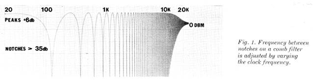
 In the phasor/flanger mode, the frequency and
its multiples whose wavelengths are equal to the time delay will be
completely cancelled out while all other frequencies are reinforced.
The result is a comb filter whose frequency between the notches is
adjusted by varying the clock frequency (Fig. 1). In this manner, a
tonal quality can be imparted to nontonal sound such as drums,
cymbals, and even voices.
In the phasor/flanger mode, the frequency and
its multiples whose wavelengths are equal to the time delay will be
completely cancelled out while all other frequencies are reinforced.
The result is a comb filter whose frequency between the notches is
adjusted by varying the clock frequency (Fig. 1). In this manner, a
tonal quality can be imparted to nontonal sound such as drums,
cymbals, and even voices.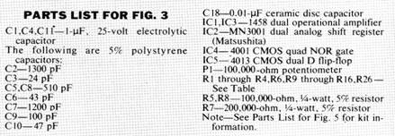 Since the audio signal at the input is being
sampled at a rate determined by the clock frequency, a theoretical
limit of half the clock frequency is the highest audio frequency
that can be reliably passed. However, owing to practical
limitations, a third of the clock frequency is a more reasonable
design goal. Circuits can be cascaded to provide longer time delays
at high clock rates, but the increase in noise in the
series-connected circuits might outweigh the increase in bandwidth.
Since the audio signal at the input is being
sampled at a rate determined by the clock frequency, a theoretical
limit of half the clock frequency is the highest audio frequency
that can be reliably passed. However, owing to practical
limitations, a third of the clock frequency is a more reasonable
design goal. Circuits can be cascaded to provide longer time delays
at high clock rates, but the increase in noise in the
series-connected circuits might outweigh the increase in bandwidth.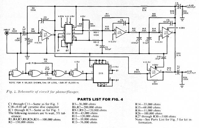
 In the phasor/flanger mode, the maximum delay
required is about 5 ms, which is short enough that a single shift
register can be used without compromising the bandwidth. The second
shift register is therefore connected in parallel with the first to
improve the S/N ratio. The signals are added in-phase, while the
noise adds and subtracts randomly.
In the phasor/flanger mode, the maximum delay
required is about 5 ms, which is short enough that a single shift
register can be used without compromising the bandwidth. The second
shift register is therefore connected in parallel with the first to
improve the S/N ratio. The signals are added in-phase, while the
noise adds and subtracts randomly.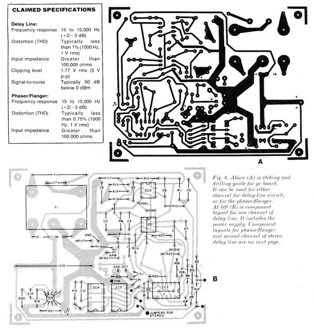
Copyright by Bill Bytheway, K7TTY February 2012