|
Automobile Locater
HAVE YOU EVER HAD TROUBLE FINDING your car in a crowded parking lot? If so, here’s a device that will be of some help.
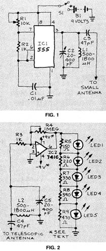
This automobile locater is made up of two parts. The first is an RF oscillator, whose circuit is shown in Fig. 1. The second is a sensitive receiver; that circuit is shown in Fig. 2.
The heart of the oscillator is a 555 timer IC. Its frequency — just below the AM broadcast-band—is determined by R1, R2, and C1. A tank circuit (C2 and L1) is used to tune the transmitter. The antenna is coupled to the transmitter through C3. Since efficiency is not very important here (output power should be kept under 100 mW), the length of the antenna can be kept short.
A telescopic antenna or a length of hookup wire will work quite well. The only thing that is important is that the antenna be vertically polarized.
At the receiver, the incoming signal is tuned by C5 and L2 before being passed on to the 741 IC. That IC amplifies the signal up to 1000 times; the amount of amplification is controlled by adjusting R4, a linear-taper potentiometer (more on that later). The five LED’s are used to indicate signal strength, they light up in order (to 5) as the signal gets stronger.
The 741 requires two 9-volt batteries for power. The positive terminal of one battery is connected to pin 7. The negative terminal of the other battery is connected to pin 4. The remaining terminals (one positive and one negative) are connected together and grounded.
Keep in mind that you will be carry ing the receiver with you as you go about your business, so it should be in stalled in a case that is as small as possible.
After the devices are built, the receiver and transmitter will need to be tuned. Once that is done, however, you should not need to do it again unless the settings are tampered with. Placing the transmitter and receiver next to each other, detune the receiver so that none of the LED’s light. Then tune the transmitter until all of the receiver’s LED’s light, indicating maximum signal strength. Potentiometer R4 should be adjusted for the minimum amplification that will give you a usable signal. Too much amplification will give you a maximum-strength indication over too wide a range. Separate the receiver and the transmitter (the farther apart they are the better) and adjust R4 until you get a maximum strength reading only when the receiver’s antenna is pointed directly at the transmitter. The RF locater is now ready for use.
Since the locater will not be able to work through the metal body of your car, you will need to set up the transmitter so that the signal can radiate through a glassed-in area. That is really not much of a problem. If you are using a hook-up-wire antenna, simply tape the free end to the top of either the front or rear windshield. If you’re using a telescopic antenna, place the transmitter on the dashboard and extend the antenna so that it is as long as possible. In either case remember to switch the transmitter on before you leave, and remember that the antenna should be aligned vertically for best results.
To find your car, just extend the telescopic antenna of the receiver to its full length and hold it parallel to the ground. Point the antenna to your far left, then swing it to your far right. Do that until you find in which direction the strongest signal lies, as indicated by the LED’s. The antenna will be pointing at your car.
Doug Krause
|
Copyright by Bill Bytheway, K7TTY February 2012