|
Bar-Graph Voltmeter for your CAR
Your cars ammeter can’t warn you about impending battery failure. But this bargraph voltmeter will help you keep tabs on your cars charging system!
STEVE PENCE
HAVE YOU EVER BEEN STRANDED IN A parking lot because of a dead battery? Nearly all of us have at one time or an other—usually at the most inconvenient time. But that situation could be easily avoided if you knew your battery’s condition.
Adding a voltmeter to your dashboard instruments is the best way to track your battery’s performance. We’ll show you how to build a voltmeter that’s a bit different from the ones you are accustomed to seeing. Instead of a traditional mechanical meter movement, this one uses a sleek-looking, easy-to-read bargraph display The display uses ten LED’s (Light Emitting Diodes) to display a voltage range from 10.5 to IS volts. Each LED represents a 0.5-volt step in voltage.
The voltmeter is designed around National Semiconductor's LM3914 dot/bar display driver. Using that IC keeps the rest of the circuit simple: only 15 passive components plus the 10 display LED’s are required.
The voltmeter circuit
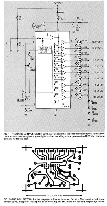
The schematic of the voltmeter is shown in Fig. 1. The heart of the circuit is IC1 the LM-39l4 dot/bar display driver. That IC contains nearly everything needed to construct a surprisingly accurate voltmeter.
As you can see from the simplified representation of the driver’s internal circuitry shown in the schematic, the device contains a precision voltage reference source that is very stable over a wide range of supply voltages and temperatures. It also has a precision voltage-divider chain made up of ten 1K resistors.
When the voltage reference is properly connected across the divider chain, 10 very accurate voltages are set up at the junctions of each of the 1K resistors. Each of these reference voltages are fed to the input of a separate comparator, which compares the reference voltage with the voltage presented to the input at pin 5.
If the input voltage is greater than the reference voltage, the comparator’s output will go low, turning on its respective LED. As the input voltage goes higher, successively higher LED’s turn on. The voltage that each LED represents is determined by the total voltage applied to the divider chain. If one volt is applied then each step will equal .1 volt.
You will note that the input voltage applied to pin 5 is first divided in half by R1 and R2. That’s because the 3914 cannot measure a voltage that is equal to its supply voltage. We use the voltage divider to cut it in half to provide plenty of head room. This means that when the battery voltage changes by .5 volt the input to the driver sees only a .25-volt change.
In order for the driver to measure in .25-volt steps we must apply 2.5 volts to the internal divider chain. That is accomplished by setting trimmer potentiometer R5 to the correct value. The internal voltage reference is set up to provide a constant current down through R5 (which is in parallel with the precision divider) and through R6. The voltage dropped across R5 is therefore also seen across the precision divider.
Resistor R6 is needed because we must begin our measurement at 10.5 volts instead of ground. That resistor essentially extends the bottom of the internal divider. The first comparator therefore turns on when the input signal is .25 volt above the voltage seen at the top of R6. If the constant current from the reference source is set to provide a 5.0-volt drop across R6, then the first comparator will turn on when the input voltage is equal to 5.25 volts (which corresponds to a battery voltage of 10.5 volts that is divided in half).
Trimmer potentiometer R5 is next adjusted to so that 7.5 volts is applied to the top side of the divider. You now have 2.5 volts across the divider for the required .25 volt per step. Since the current through R5 and R6 is constant, the voltage dropped across R6 will be constant, even if the value of R5 is changed.
Resistor R7 and diodes D2 through D5 clamp the voltage applied to the LED’s to about 3 volts. This limits the power that the driver IC must handle and improves measurement linearity.
The electrical systems of most automobiles are extremely noisy, often producing narrow spikes as much as 200 volts in amplitude. Spikes of that magnitude can easily ruin a project of this nature if precautions are not taken. A low pass filter made up of L1 and C2 guards against voltage spikes. Diode D1 is used to protect against reverse voltage in case the voltmeter is hooked up backward. Although those three components are not required for the voltmeter to operate, you should install them. They do increase long term reliability.
Building the voltmeter
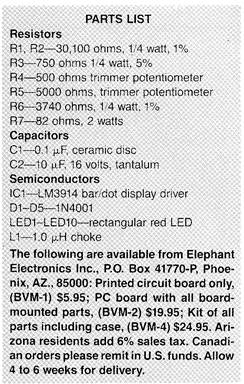
The bargraph voltmeter is easy to build. It’s made up of a printed-circuit board, one integrated circuit, and a few discreet components. A PC board is not essential, but it certainly is a convenience. A foil pattern for a board is shown in Fig. 2. You can, however, build the meter using pre punched circuit board and point-to-point wiring techniques. The layout of the circuit is not critical. The parts are available from a large number of electronics distributors or from the source listed in the parts list.
Once you have all the parts together, you can begin assembly by installing the components by following the parts placement guide of Fig. 3. Remember that the diodes, the LED’s, and capacitor C2 are polarized and must be installed in the correct direction.
When installing the LED’s be sure they are all placed the same height from the PC board (approximately .150 inches). That’s most easily done by having someone hold the board for you while you solder them into place. Have him hold the board foil side up, with the LED’s installed over a flat surface. That will force the faces of all the LED’s to be at the same height from the board. After they are all soldered in, bend them over so they are parallel to the surface of the board (see Fig. 4).
If you have access to different-colored LED’s, you might consider installing them to signal different voltages. For ex ample, yellow could represent anything under 12 volts, green could indicate inputs between 12 and 14 volts, and red could be used to indicate that your battery is over charging.
Don’t forget to install the jumper wire, J1, on the printed circuit board. That programs the LM3914 to display in the bar mode. If, on the other hand, you prefer the dot mode (in which only one LED at a time comes on) simply leave the jumper out.
Calibrating the meter
Calibration is easy to do—but it does require the use of an accurate voltmeter as a reference. The calibrating meter should be able to read to within at least .1 volt on a 10-volt range.
Preset variable resistors R4 and R5 to the center of their range. Connect the meter to a source between 12 volts and 15 volts. With your calibrating voltmeter, measure the voltage from pin 4 of the IC to ground (across resistor R6). Adjust R4 for exactly 5.0 volts at this point.
Next measure the voltage from pin 8 of the IC to ground (across R5 and R6). Adjust R5 for exactly 7.5 volts. The two adjustments should not interact, but recheck the voltage at pin 4 just to be sure.
Installing the voltmeter
Mechanically, there is only one thing you have to keep in mind when installing the voltmeter: In order for the display to read from left to right, the PC board must be mounted with the foil side up.
Many cars come equipped with an ammeter to indicate charging is taking place. Although this tells you that the alternator is charging, it does not tell whether or not the battery is accepting the charge. A voltmeter on the other hand lets you know immediately what is happening in the charging system. It can give you advanced warning that your battery is on the way out.
If your battery is fully charged, the engine is not running, and no accessories are on, you should measure 12 to 12.5 volts. If the battery is placed under load by turning on the headlights the voltage should drop only a half a volt or so. After starting the engine, the alternator will quickly bring the battery voltage up to 13 or 14 volts if the system is charging properly.
If the alternator voltage were to rise more that 2 volts above the battery volt age, it would indicate overcharging. One possible reason could be a bad voltage regulator ground. Overcharging will cause excessive boiling of the electrolyte and warping of the plates. That can lead to internal shorts.
If the battery isn’t holding a charge properly, it is easily detected by checking the voltage just before starting the engine. If the voltage has dropped to 11 volts or less overnight, you may soon be stuck in a parking lot somewhere.
One of the real advantages to the voltmeter is that you become accustomed to the normal pattern of voltage fluctuations. When a problem rears its head, the pattern will change and you then have an early warning of impending doom.
|


Copyright by Bill Bytheway, K7TTY February 2012