|
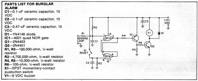
Burglar Alarm
This burglar alarm circuit uses one integrated circuit and operates from a 6 volt battery. It is activated upon the breaking of a circuit, there is virtually no limit to the length of wire you can use. You can protect every window and door in your house. Practical operation by using four D cells for power is accomplished through the use of a four-section CMOS integrated circuit which draws only a few microamperes from the battery. Thus~ battery life will be equivalent to its shelf life unless the alarm is activated. The heart of the circuit is a pair of NOR gates connected in a bistable configuration called a flip-flop or latch circuit. When the circuit is in standby, pin 1 of IC1 is held to almost zero volts by the continuous loop of sensing wire. This causes pin 3 to assume a voltage of 6 volts, cutting off Q1 and Q2. When the sensing circuit is broken, C1 charges to battery voltage through R2. This causes the latch circuit to change state and pin 3 goes to zero volts. Bi becomes forward-biased through R4 and turns on Q2 which operates the buzzer. The circuit will remain in an activated state once the alarm is set off, even though the broken circuit is restored. A reset switch has been provided to return the latch circuit to its original state and shut off the alarm.
|
Copyright by Bill Bytheway, K7TTY February 2012