|
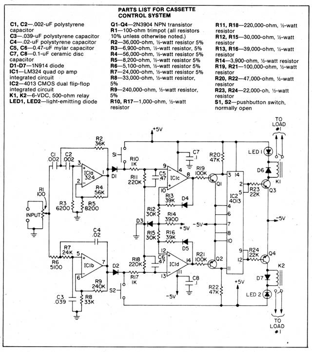
Cassette Control System
Let’s say that you need a programmable control system that can perform a timed sequence of operations. This sounds like a job for a high priced computer, doesn’t it? In many instances, however, just a cheap cassette recorder can do a respectable job—provided, of course, that you build this 2-channel controller.
High-frequency signals (above 5000 Hz) at the controller’s input are amplified by high-pass filter IC1-a; then detected and used to clock one half of a dual flip-flop (U2). Each tone burst toggles the flip-flop, causing relay K1 to alternately open and close. These high-frequency audio signals have no effect on low-pass filter U1 b, but frequencies below 500 Hz will produce the same effect in the lower channel as high frequencies in the upper channel, with the result that K2 alternately opens and closes a burst of low frequency audio.
Feed the signal from your recorder’s speaker output jack to the controller’s input. Record a short sequence of tones—about 300 Hz for the low channel, and 7500 Hz for the high channel. Play back the tape-recorded sequence, and adjust R1 somewhat past the point where toggling of the relays starts. The LED go on and off with the relays and serve as convenient indicators of channel activity. Pushbuttons S1 and S2 can be used to change the status of a channel independently of the audio input. Whistles, tuning forks and electronic oscillators can all be used as tone sources. Whichever you use, strive to keep the level of the recorded signal constant.
|
Copyright by Bill Bytheway, K7TTY February 2012