|
Clipping Indicator
THE CONSEQUENCES of overdriving an audio power amplifier can range from the unpleasant (ragged, distorted sound) to the catastrophic (burnt, black remains of tweeters and super tweeters). It’s obvious, therefore, that the audiophile will want to avoid this condition. The project presented here, an Amplifier Clipping Indicator, will help him do just that. It continually senses both the audio output of the amplifier and the power supply voltages, and flashes a warning LED if the output signal voltage approaches either power supply rail. The user can then reduce the drive level so that the LED stops flashing.
Readily available, inexpensive components comprise the Amplifier Clipping Indicator. Many of them will be found in an experimenter’s junk box. A stereo version can be built in just a few hours, making the Amplifier Clipping Indicator an enjoyable weekend project. The modest amount of power the circuit re quires can be tapped from the power amplifier’s supply or furnished by a small supply built especially for this purpose.
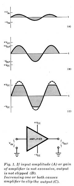
What Is Clipping? When an audio amplifier is overdriven, it “clips” the in put signal. The process is shown graphically in Fig. 1. A power amplifier is driven by a sinusoidal input signal having maximum positive and negative amplitudes of +Vin and —Vin, respectively (Fig. 1A). The amplifier generates an output signal that is (ideally) an exact replica of the input except for its increased amplitude.
Because the amplifier must reproduce ac waveforms, it employs a bipolar dc power supply. This means that the most positive voltage it can produce at the output terminals is +VCC, and the most negative voltage is —VCC. If the amplifier’s gain control is adjusted so that the output signal approaches the limits imposed by the power supply, a waveform like that shown in Fig. 1 B is generated. It can be seen that the maximum positive and negative swings of the output volt age, +VOUT and —VOUT, are some what less than the absolute limits of +VCC and -VCC.
Adjusting the control for more gain causes the amplifier to attempt to exceed the constraints of the power sup ply. The result is a clipped waveform like that shown in Fig. 1C. Spectral analysis of such a waveform indicates the presence of high-order harmonic distortion products during the interval that clipping takes place. If the output signal is clipped less than 1% of the time, the effect is usually inaudible. As the duration of clipping approaches 10%, the usual consequence is audible, “raspy” distortion. A severely clipped signal (more than 10% of the time) contains a considerable amount of high-frequency energy. This energy poses a significant threat to midrange and high-frequency drivers because it is directed to them by the crossover network and they are usually capable of dissipating far less power than bass drivers.
Although the example that has been discussed used sinusoidal signals, an audio amplifier usually processes musical signals that are much more complex. It is characteristic of most recorded music that the average signal level is low. However, musical program material does contain a significant number of short-lived, high-level transients. An amplifier might be called upon to deliver one watt of output power on an average basis, but accurate reproduction of a bass percussion transient can require fifty to one-hundred times that power level for a brief instant.
All is well if the amplifier has enough voltage and current reserves to pass the transient unclipped. However, if the amplifier cannot do so, the dynamic range of the recording will be compressed and audible distortion products introduced. This, coupled with the fact that perceived loudness is a function of average (as opposed to peak) power, explains the trend toward power output capabilities that were unheard of in audio amplifiers a relatively short time ago. So called “super-power” amplifiers allow the audiophile to listen to program material at realistic levels without clipping high-level transients, even if inefficient speakers are used.
About the Circuit. The Amplifier Clipping Indicator is shown schematically in Fig. 2. Each channel of amplification in a sound system will require a separate indicator circuit. The most common application for the project is in a stereo system, so component numbers for two channels are shown. Those for the right channel are given in paren theses. The discussion that follows pertains to only one channel, designated the left channel of a stereo pair. Every thing that will be said, however, applies equally to as many channels as are needed because the indicator circuit is identical for each.
Output signals from the audio amplifier are applied to an 11:1 voltage attenuator (R1R3). Similarly, the positive and negative supply voltages, +VCC and —VCC, are applied to attenuators R5R7 and R9R11. The voltage dividers associated with the power-supply outputs, however, employ trimmer potentiometers and have variable attenuation factors. Those portions of the input volt ages passed by the attenuators are applied to two 741 operational amplifiers (IC1A and IC1B) employed as voltage comparators.
Assume that the trimmer potentiometers have been adjusted to attenuate the power supply voltages slightly more than the fixed divider attenuates the audio signal. If the amplifier is being driven by an audio signal, but not to the point of clipping, its output voltage will be smaller in magnitude than either the positive or negative supply voltage. This means that the voltage applied to the noninverting input of IC1A is never more positive than that applied to the inverting input, and the output of the comparator remains at —12 volts.
Similarly, the voltage applied to the inverting input of IC1B remains positive with respect to that present at the noninverting input, keeping the output of IC 1B at —12 volts.
Diodes 01 and 03 form an OR gate whose output goes to +12 volts when either of the comparator outputs does. In the absence of clipping, both D1 and 03 are reverse-biased, which keeps transistor 01 cut off. Monostable multivibrator IC3 remains untriggered and its out put (pin 3) is at ground potential. This keeps 07, which together with 05 forms a second diode OR gate, in a nonconducting state. The output of the 0103 OR gate is applied to the 05 input of the second gate. Both inputs are low, so Q3 receives no base drive and the clipping indicator LED (LED 1) remains dark.
Now let’s assume that the audio amplifier is driven into clipping. The audio output voltage reaches the positive or negative supply voltage (or both) and is clipped like the one shown in Fig. 1C. When the positive portion of the audio waveform applied to the noninverting in put of IC1A becomes more positive than the voltage at the inverting input, the output of the comparator goes to +12 volts, this forward-biases D1 and 05, and provides base drive for 01 and 03. A similar thing happens when the negative portion of the audio waveform is clipped. The voltage applied to the inverting input of IC1B becomes more negative than the voltage at the noninverting input, so the output of this comparator switches to a +12-volt level. This forward biases 03 and 05, providing base drive for 01 and 03.
When 03 is supplied with base cur rent, it turns on and the clipping indicator LED glows. However, the clipping interval can be so short that the eye will not readily detect the brief flash of the LED. That’s why 01, IC3, and their associated components have been included. Together they function as a pulse stretching circuit. Here’s how.
When the output of either comparator goes high, 01 receives base current and its collector drops to ground potential. A negative pulse is passed by C1 to pin 2 of IC3 triggering this monostable multivibrator. The output of the timer IC (pin 3) goes high for an interval determined by the time constant of R19C5. For the values given, the width of the output pulse is about 0.25 second. This output pulse is OR’ed with the output of gate 0103 and applied to resistor R21. Transistor 03 receives base drive and sinks current for LED1, causing the clipping indicator LED to glow.
The pulse-stretcher turns the LED on for one quarter of a second even if the clipping interval is much shorter. A subsequent trigger pulse received while the monostable is timing will not retrigger it. However, one received immediately after a timing cycle will cause the process to be repeated. If the clipping interval is longer than the width of the out put pulse (which can be extended to any desired interval by increasing the value of R19 or C5 or both), the OR’ing action of 05 and 07 will keep 03 in a conducting state. Therefore, the clipping indicator LED will continue to glow even after the output of the monostable has returned to its ground state. It will glow until the audio amplifier recovers from the clipping condition.
The project requires a bipolar power supply of ± 12 volts dc. These operating voltages can usually be tapped from the audio amplifier’s power supply. Zener diodes and series current-limiting resistors can be used to drop the amplifier’s +VCC and —VCC supply voltages to the desired values. Alternatively, a small line-powered supply can be built into the project’s enclosure. Current demand is relatively modest—a few milliamperes for the —12-volt supply and about 50 mA from the positive rail.
Because dynamic voltage comparison is the method employed to sense clip ping, this project enjoys a significant advantage over such power-monitoring devices as peak-reading meters and strings of LEDs. A peak-reading meter only indicates that the audio output has reached a given level. It will not necessarily indicate that clipping is taking place. For the sake of illustration, let’s consider what happens to an amplifier with an unregulated power supply when it is driven by an audio signal with many high-level transients.
Suppose that our amplifier can deliver 75 watts per channel of continuous power to 8-ohm loads and has an IHF dynamic headroom of 2.04 dB. This means that it can deliver 120 watts of output power into 8 ohms for brief intervals. Consequently, the power supply volt ages under full load are + 34.6 volts and —34.6 volts. When the demand on the power supply is light, the available volt ages are +43.8 and —43.8 volts.
If the supply’s filter capacitors have charged up to these higher voltages and a short-lived, high-level transient arrives at the amplifier’s audio input, the output stage can momentarily generate an 87.6-volt peak-to-peak waveform with out clipping it. However, driving the amplifier this hard causes the voltages across the filter capacitors to decrease. If the amplifier is called upon to re produce a second high-level transient before the filter capacitors have had an opportunity to recharge sufficiently, clip ping will result.
It can thus be seen that a peak-reading audio power meter will not necessarily indicate that the amplifier is clipping. In our example, the lowest possible power supply voltages are +34.6 and —34.6 volts, so we can safely say that any audio output signal with a peak power of up to 75 watts as indicated on the peak-reading monitor will not be clipped. Above that power level, however, the meter reading alone will not tell us whether clipping is taking place. By contrast, a flash of the indicator LED in this project warns of the onset of clipping, a warning which takes into account the dynamics of the amplifier’s power supply.
Construction. Either printed circuit or perforated board can be used in the assembly of the Amplifier Clipping Indicator. In any event, the use of IC sockets is recommended. Be sure to use the minimum amount of heat and solder consistent with the formation of good solder joints. Also, observe the polarities and pin basings of semiconductors and electrolytic capacitors.
After the project’s circuit board has been completed, connect it to BTS1 and the indicator LED(s) with suitable lengths of hookup wire. Then secure the board to the project enclosure with standoffs and machine hardware. Mount BTS1 on the rear panel of the enclosure with machine hardware and the indicator LED(s) on the front panel with rubber grommets or mounting collars made especially for this purpose. As mentioned earlier, operating power for the project can be obtained from a small supply included inside the enclosure or tapped from the amplifier itself if a bipolar dc supply is employed. If the latter approach is taken, the required zener diodes and series resistors will easily fit in side the project enclosure.
Another possible approach, if there is room in the amplifier chassis, is to mount the entire project inside the amplifier and locate the indicator LEDs on the front panel. If this is done, BTS1 can be eliminated and the connections to the speaker outputs and +VCC and —VCC hard-wired.
Note that the circuit as shown will function properly with audio amplifiers having supply voltages of up to ±60 volts (or +80 or —80 volts in the case of an amplifier with a single-ended supply). That bipolar voltage corresponds to a clipping power of 225 watts into 8 ohms. The project is therefore useable with the vast majority of audio amplifiers commercially available. If you have an amplifier employing greater supply voltages, the circuit can be suitably modified simply by increasing the attenuation factors of the input voltage dividers (increasing the values of R1, R5, and R9).
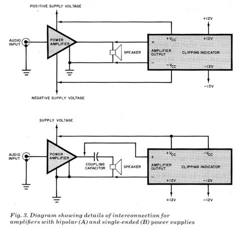
Interconnection and Adjustment. If your audio amplifier employs a bipolar dc power supply (most do), connect the +VCC and —VCC terminals of BTS1 to the power supply outputs inside the amplifier. (Note that making these connections will, in most cases void the warranty on your amplifier.) Also, connect the AMPLIFIER OUTPUT terminals of BTS1 to the amplifier’s speaker output terminals in agreement with the polarities indicated in Fig. 2. These connections can be made with standard “zipcord” or speaker wire. Refer to Fig. 3A for details.
Slightly different connections should be made if your audio amplifier employs a single-ended power supply and a coupling capacitor or transformer between the final amplifying devices and the speaker output terminals. The required connections are as follows: connect the +VCC and —VCC terminals of BTS1 to the “hot” side of the power supply out put; and connect the “hot” AMPLIFIER OUTPUT terminal of BTS1 to the “hot” side of the amplifier output before the output coupling (dc blocking) capacitor or transformer. Refer to Fig. 3B.
The circuit’s trimmer potentiometers can now be adjusted. Referring to Fig. 2, note the points near R7 and R11 designated A, B, and C. If your audio amplifier has a bipolar power supply, adjust the wiper of R7 so that it is at position A and the wiper of R11 so that it is at position B. If your amplifier’s power supply is single-ended, adjust the wiper of R7so that it is at position A and the wiper of R11 so that it is at position C.
Two pieces of test equipment are needed to adjust the trimmer potentiometers properly. The first is a sine-wave generator whose output is of sufficient amplitude to drive the audio amplifier into clipping. (One volt peak-to-peak of drive signal is usually more than adequate.) The second item can be either an oscilloscope or a multi meter, but the former is preferred. We will first describe the procedure to be followed if an oscilloscope is available and then that to be employed if one is not.
Connect a patch cord between the output of the signal generator and the in put of the audio amplifier. Then connect the probe running from the oscilloscope’s vertical amplifier input to the audio output of the power amplifier. Apply power to the project, signal generator and audio amplifier. Then adjust the amplitude of the generator’s output, the gain of the audio amplifier, and the various oscilloscope controls for a stable, sinusoidal trace. The output of the audio amplifier should not be connected to a speaker.
Increase either the gain of the amplifier or the amplitude of the generator out put until the oscilloscope trace just be gins to reveal clipping of the waveform. Then decrease either the amplifier gain or signal output so that the amplitude of the waveform decreases a few volts be low each clipping limit. (This provides a small safety margin so that the indicator LED will start to flash just before clipping actually begins.)
Without disturbing the amplifier, generator, or oscilloscope control settings, adjust trimmer R7 until the LED starts to flash on positive signal peaks. Make a pencil mark on the circuit board denoting the correct position of the wiper and then return the control to its original setting. Next, adjust R11 so that the indicator LED starts to flash on negative signal peaks. Once the correct setting of R11 has been found, don’t disturb it. Return to R7 and adjust its wiper so that it corresponds to the position marked on the circuit board. Decrease the amplitude of the generator output or the gain of the amplifier, noting that the indicator LED will be extinguished. If you have built more than one Amplifier Clipping Indicator, say, for use with a stereo or four-channel audio amplifier, repeat the procedure just described for each.
Those who do not have access to an oscilloscope can use a VTVM, VOM, or similar multimeter to adjust the project. First, the power supply limitations of the amplifier with which the project will be used must be determined. Connect the signal generator to the amplifier as described above and adjust the generator for a 60-Hz output. Connect the amplifier’s speaker output to an 8-ohm load (a resistor is best) and apply a moderate amount of drive to the amplifier input. With the power supply loaded, measure its output voltage(s). Increase the gain of the amplifier or the amplitude of the drive signal and note whether the power supply voltages decrease. If they do, mea sure the minimum values.
Having performed these measurements, determine the peak-to-peak voltage swing that the output can generate. For example, if the minimum voltages that a bipolar power supply generates under maximum drive conditions are +30 and —30 volts, the continuous peak-to-peak signal that the amplifier can pass at the on set of clipping is 60 volts p-p. Next, calculate the rms output voltage using the equation Vrm, = Vpp/2.2828 For our example, the rms output voltage is 21.2 volts.
Connect the multimeter probes across the 8-ohm load and adjust the amplifier’s gain or the amplitude of the input signal so that the calculated rms voltage is indicated by the meter. Then decrease the gain or the drive signal so that the meter reading is a few volts below the calculated value. (This pro vides the safety margin previously discussed.) Now adjust the trimmer potentiometers in the same manner described in the procedure employing the oscilloscope. Repeat the procedure for each additional channel of amplification (if any).
Use. The Amplifier Clipping Indicator is now ready for use. With it, you’ll be able to adjust drive level and/or amplifier gain so that your amplifier will never go into heavy clipping. Keep in mind that the indicator LED will begin to flash slightly before the on set of clipping. If the LED starts to blink, back off on the drive level or gain control. Your high-frequency drivers will b glad you did! |
 To
protect speakers, this simple circuit senses power supply voltages
and flashes a warning L ED just before the onset of clipping
To
protect speakers, this simple circuit senses power supply voltages
and flashes a warning L ED just before the onset of clipping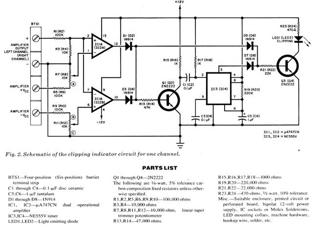
Copyright by Bill Bytheway, K7TTY February 2012