|
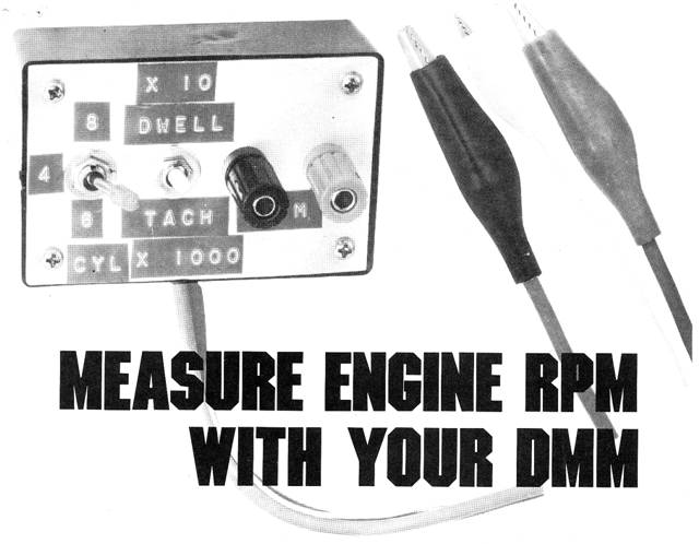
DMM Tachometer
Black box tach / dwell adapter helps you tune up 8 6 4 cylinder auto engines quickly with the help of your digital voltmeter.
RAY CHANDOS A GOOD TACH/DWELL METER IS AN ESSENTIAL TOOL for automotive tune-ups. The tachometer function is used to set or monitor engine speed during ignition timing and carburetor adjustments. The dwell meter aids in setting the breaker-point spacing in cars that still have them.
The simple device described here turns your DMM into an accurate tach / dwell meter with direct digital readout in RPM or degrees of dwell. Though costing less to build than a self-contained analog-readout type, this unit provides greater accuracy and readability. Four-six-or eight-cylinder engines can be tested, with power for the device supplied by the car’s battery. Circuit operation
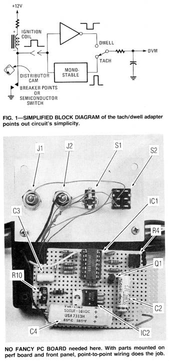
A simplified diagram of the tach / dwell
adapter is shown in Fig. 1. The input signal, taken from the
negative (—) side of the car’s ignition coil, is high while the
breaker points are open and low while they are closed (the dwell
time). That signal is fed to an inverter, whose output goes high
when the points are closed, producing a rectangular waveform whose
average value is proportional
For the tach function, the input is also sent to a monostable multivibrator. The monostable’s output is a constant-width pulse, resulting in a waveform whose average DC value is proportional to the number of pulses per minute, or engine RPM. After RC filtering, that signal can be read by the DVM.
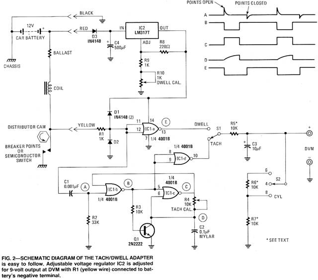
In the complete circuit, shown in Fig. 2. resistor R1, together with diodes D1 and D2 protect the IC from high-voltage input transients. The monostable multivibrator is made from IC 1-b and c. It delivers an out put pulse that has a width of about 3.33 ms, set by the R4-C2 time constant. Transistor Q1 quickly discharges C2 at the end of the timing period so that the monostable can be immediately retriggered by the next input pulse without error. IC1-d buffers the monostable’s output pulse, while IC1-a is the inverter for the dwell function.
Switch S1 selects either the tach or dwell waveform and passes it to filter network R5-C3 for smoothing. Resistors R5, R6, and R7 then act as a voltage divder to scale the selected output signal for direct reading in either RPM or degrees. Switch S2 sets the correct scaling for four - six - or eight - cylinder engines.
Power for the circuit comes from the car’s battery, with diode D3 protecting against accidental polarity reversal. Capacitor C4 filters the voltage, and IC2 regulates it to a constant value of about +9V.
Construction is straight forward
Circuit layout is not critical and normal assembly techniques can be used. ¼-watt, 5% resistors may be used throughout, but R5, R6, and R7 must be either 1% types or 57 types selected for closely matched values. Also, for accurate monostable timing, C2 should be a Mylar type and IC1 a B-series 4001.
Switches are mounted on the front cover of a suitable enclosure, with the three color-coded leads passed through a hole in the back or side. Large alligator clips are used for the battery connection, and a small alligator clip for the coil connection. Rubber feet or suction cups can be mounted on the back to prevent scratching the car’s finish.
Calibration is fast and easy
Potentiometer R10 is used to calibrate the dwell function. Set S1 to DWELL, S2 to 4 CYL, and connect the red and black leads to the car’s battery. It is not necessary to start the car. Connect the yellow wire to the negative (—) battery post, the DVM to the output terminals, and adjust R10 for a reading of exactly +9V (90 degrees of dwell), if resistors R5, R6, and R7 are properly matched, you should now read 4.5V (450) on the 8 CYL position, and 6V (600) on the 6 CYL position of S2.
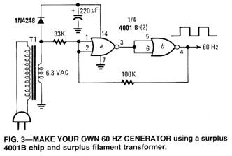
Now connect the yellow lead to a source of 60-Hz, 12V pulses. A bench signal generator (monitored by an oscilloscope set to line sync), or the circuit of Fig. 3 may be used. Be sure to ground the generator to the unit’s ground. With S1 on TACH and S2 on 4CYL. Adjust R4 for a DVM reading 1.8V (1800) RPM.
Now put it to work
The tach/dwell adaptor can be used with both electronic or mechanical-type ignition systems, although dwell is actually a meaningless quantity for breaker less ignitions. Simply connect the red and black wires to the battery, and the yellow wire to the negative (—) terminal or the ignition coil. Set the switches for the desired function and number of cylinders, connect the DVM to the output terminals, and start the engine. You will have to multiply the voltage reading by 1000 for RPM. and by 10 for degrees of dwell. Thus, a DVM reading of 3.25V indicates an engine speed of 3250 RPM, or a dwell angle of 32.50.
Of course, the DVM should be set on the most sensitive usable range, for greatest precision. An analog meter with a high input resistance could also be used if a DVM is not available. Range of measurement exceeds 8000 RPM on the four-cylinder range, well beyond the red line of most engines. |

 A
word of caution and some advice is needed here. Be extremely careful
when connecting leads to engine. Should they get caught in the fan
or pully system, the engine will suck up your equipment, and maybe
you. Attach a terminal lug to the spark coil breaker terminal to
facilitate easy and frequent connection.
A
word of caution and some advice is needed here. Be extremely careful
when connecting leads to engine. Should they get caught in the fan
or pully system, the engine will suck up your equipment, and maybe
you. Attach a terminal lug to the spark coil breaker terminal to
facilitate easy and frequent connection.Copyright by Bill Bytheway, K7TTY February 2012