|
DIGITAL AUTOMOTIVE TUNE-UP METER
Use it to measure and adjust dwell, rpm, voltage on your car, boat, cycle, or lawn mower.
It’s costly to have a mechanic tune up your automobile regularly so that it can run smoothly and use gasoline efficiently. You can do it yourself, however, with no great investment in tools or training. All that’s generally needed is a single combination instrument that will measure dwell angle, engine rpm, and voltage.
Such an instrument is the DATUM (Digital Automotive Tune-Up Meter) described here; Featuring a digital read out, it’s easier to use and is capable of better accuracy than analog-type meters since there are no scales to be interpolated and there’s freedom from parallax error. Cost to build is only about $70.
The DATUM uses a 3-digit, 7-segment LED display, and can measure 0 to 9999 rpm, dwell angles from 0 to 99.9 and dc levels from —9.9 to 99.9 volts. The instrument is compatible with most factory and add-on electronic ignition systems, as well as conventional Kettering (points/breaker) ignition. Any engine (4-, 6-, or 8- cylinder, 2 or 4-stroke) can be tuned up using this instrument. Therefore it is useful for motorcycles, boats and lawn mowers, as well as cars.
Circuit Operation.
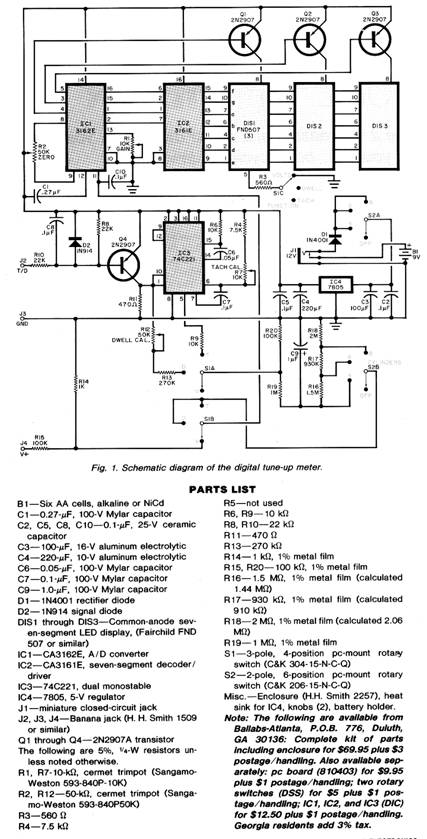
The basic voltage measuring circuit (Fig. 1) is designed around IC1 a dual-slope, A/D converter, and IC2, a BCD-to-seven-segment decoder/driver. The latter drives the parallel-connected segments of DIS1 through DIS3, while Q1 through Q3 provide the digit enable. This chipset, originally developed for an RCA digital voltmeter, provides a full-scale sensitivity of 999 mV and is used for all DATUM measurements: VOLTS, DWELL, and TACH (rpm). In the VOLTS mode, the input signal applied between J4 and J3 is scaled by a 100:1 precision divider (R14 and R15) to yield a full-scale read ing of 99.9 V. In this mode, SIC provides the decimal point via R3.
The TACH and DWELL modes share a common conditioning stage (C8, R10, D2, R8, and Q4) in which the input signal from the distributor is standardized in height and shape. In the DWELL mode, the low-impedance output from the collector of Q4 (across R11) is routed via DWELL CAL potentiometer R12 and series resistor R13 through switch S1A to the network consisting of R16 through R20 and C9 which averages the value of the distributor duty cycle. Scaling is achieved by R19 and R20 in conjunction with the precision divider network R16, R17, and R18. The proper scale factor is selected by S2B for 4-, 6-, or 8-cylinder engines. The signal selected by SI is then applied to the input of IC1.
In the TACH mode, the signal from Q4 triggers one-shot multivibrator IC3 with each point closure. Extraneous triggering from the ignition system ringing is avoided by using a second one-shot with in IC3 to disable the first when the points open. A CMOS one-shot is used because a MOSFET device output does not have the inherent Vcc (SAT) offset of bipolar devices. The CMOS thus allows proper zero. The tachometer signal is also routed via R9 and S1 to C9 for averaging, and application to the dc voltmeter chipset.
Five-volt operating power is provided by regulator IC4, which is driven from battery B1 or an external 12-V input applied via J1. Diode D1 protects the circuit from accidental reverse voltage application at J1.
Construction.
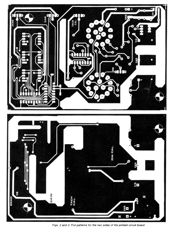
Although the circuit can be hardwired, the use of a double sided glass-epoxy pc board (as shown in Figs. 2 and 3) is suggested. Two separate pc boards can be fabricated (one for the top and the other for the bottom foil pattern) and used “back-to-back” with interconnections between the boards made via the component leads and IC socket pins (the three ICs should be mounted in sockets). In either case, drill all required holes.
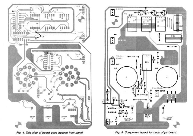
Mount the components on the two sides of the pc board as shown in Figs. 4 and 5. Observe correct component polarity, soldering on both sides of the pc board where required. Make sure that there are no solder bridges between adjacent copper traces. Since IC1, pin 11, has a very high input resistance (approximately 100 megohms), be certain all solder flux is removed from between this IC socket pin and adjacent foil traces. Other than the ICs that will be plugged in later, the remaining semiconductors—including the three displays — can be soldered in place. Check that the displays are properly oriented.
Before installing the rotary switches suggested for S1 and S2, note that they have adjustable stops. These are set for the proper number of positions by removing the nut and washer and repositioning the stop tab. The circuit board has been designed so that the switches called for in the Parts List cannot be improperly installed. Drill the three 25/ 64” holes shown in Fig. 4 for easy wiring to the three front-panel input connect ors: T/D, GND, and v+.
The finished pc board can be tested, before final installation, by connecting a 12-volt dc source across the proper J1 inputs (Fig. 5).
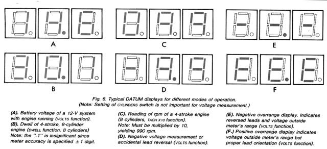
Look for 5 volts at the output of volt age regulator IC4. If this voltage is present, temporarily short pins 10 and 11 of IC1. The display may show a three-digit number (see Fig. 6F), positive over range, or a minus sign and two digits (or Fig. 6E) negative over range. In either case, adjust ZERO potentiometer R2 until the display shows 000. If any digits or segments are missing, check all connections to IC1, IC2, the digit driver transistors, and the displays.
Once the pc board is working, then the front panel can be drilled. (Note that the board is slightly smaller than the front panel of the suggested enclosure). Using the finished board as a guide, drill holes for J1, J2, J3, and J4, the two switches, and a rectangular cutout for the three displays. The display opening is covered with a piece of polarizing filter that’s epoxied on the rear of the front panel.
After cutting the two switch shafts to length, knobs are installed, and each stop position is identified. The six AA cells are installed in a battery holder secured to the bottom of the enclosure housing. Suitable lengths of color-coded lead connect the battery to the pc board. Diode D1 prevents damage in the case of inadvertant reverse-polarity installation. Before securing the board to the enclosure, test and calibration procedure should be done, as follows.
Test and Calibration.
With the DATUM powered from either the internal battery, or from a 9-to-I 5-V external dc source at J1, note that the three displays illuminate. If 000 is not lit, readjust ZERO potentiometer R2 for this display.
Apply a known dc voltage (less than 99.9 V) to GND (J3) and V+ (J4). Adjust GAIN potentiometer R1 until the display indicates the known input volt age (do not readjust ZERO control R2). Error displays indicating an over voltage condition and/or lead reversal are as shown in Fig. 6E and Fig. 6F.
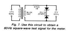
If any variation is greater than one count in the 6 or 8 CYLINDERS position, check the divider network of R16, R17, and R18, To verify the conditioning and averaging circuit, use the test signal source of Fig. 7 connected between the T/D and GND connectors. The display should show one-half the previously mentioned indications.
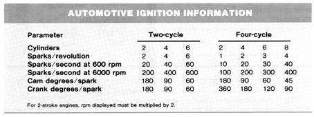
The circuit of Fig. 7 can also be used to check the tachometer portion of the DATUM. The TACK X10 display (rpm) is derived from (600 x frequency of test generator)/(sparks/second at 600 rpm). Since the output frequency of the test circuit is 60 Hz, and there are 40 sparks per second at 600 rpm for an 8-cylinder 4-stroke engine, the formula yields 900 rpm. The Table gives some pertinent engine ignition information.
With the test generator connected to the T/D and GND front-panel connectors, place the CYLINDER switch at 8 and the FUNCTION switch at TACH X10. Adjust TACH CAL potentiometer R7, for a display of 090. Note that the least-significant digit is not displayed, and all rpm values must be multiplied by 10 in this mode. With the CYLINDER switch set to 6, the display should show 120; when set to 4, the display should read 180.
Once calibration has been performed, place a small drop of adhesive or nail polish on each rotating shaft of the calibration potentiometers to eliminate the possibility of motion with vibration.
The DATUM is used in much the same way as any conventional analog tune-up meter. Space does not permit detailed information on all ignition systems, so only three basic systems will be referred to as examples (Fig. 8). Here are the basic tune-up procedures as related to the DATUM:
Always refer to your owner’s manual, shop manual, or engine nameplate for the specifications applicable to your vehicle, bike, or boat. Obtain manufacturer’s literature for add-on capacitive discharge ignition (CDI) systems.
For continuity checks, use only the Datum’s batteries and disconnect the negative lead of the vehicle battery.
Our discussion assumes a negative ground system. For positive-ground systems, all lead connections mentioned here should be reversed.
Some 24-V systems may have different specifications. Refer to the owner’s manual.
Dwell, rpm, and timing are interactive. Dwell should be adjusted before timing since the dwell angle will affect the timing measurement. The best procedure is to repeat all measurements in sequence, trimming the adjustments until all readings are correct.
Continuity Checks.
Although the DATUM does not have an ohmmeter function, it can still make continuity checks on wiring, bulbs, fuses, and diodes. Position the CYLINDERS switch to 8, and with the leads plugged into the T/D and GND jacks and shorted together, the DATUM should display 45.0
To check for continuity, connect the leads across the bulb, fuse, or diode of interest. A “good” fuse, bulb, etc., will display 45.0, while a defective or open unit will display 00.0 A “good” diode will indicate 45.0 in one direction and 00.0 with the leads reversed. All bulbs, fuses, and diodes should be checked out of circuit to obtain valid readings.
Voltage Checks.
The DATUM can measure voltages from —9.9 to 99.9 V dc with the test leads connected to the v+ and GND jacks. Negative over range is indicated by three minus signs and a decimal point (Fig. 6E), while positive over range is shown by three Es and a decimal point (Fig. 6F).
With the engine off and no load, the normal battery voltage in a 12-V (6-V) system should be between 12.2 (6.1) V and 12.8 (6.4) V. Readings below these values indicate a need for battery or charging-system maintenance.
Battery voltage drops significantly during cranking due to the high current drawn by the starter motor. In cold weather, this current is even higher because of bearing shrinkage and in creased oil viscosity. An adequate 12-V (6-V) battery will measure about 9.5 V (4.75 V) during normal engine cranking at 2YC. Lower voltage measurements may indicate a defective battery, corroded battery posts (or cable), a worn starter, or improper ignition timing.
With the engine running and all accessories off, a fully-charged 12-V (6-V) battery should measure between 13.2 (6.6) and 15.2 V (7.6 V) depending upon ambient temperature. Voltage readings less then 13.2 V (6.6 V) indicate a fault in the electrical system, battery, regulator, alternator/generator, or fan belt. Measurements in excess of 15.2 V (7.6 V) indicate a defective or improperly adjusted regulator, a defective battery, or wiring problems.
Dwell Measurements.
Dwell refers to the amount of time the distributor points (or an equivalent electronic switching circuit) remains closed, supplying current to the ignition coil’s primary winding. When the points open, the magnetic field created by the primary coil winding collapses, inducing a high voltage in the secondary winding that provides the spark. In capacitive discharge ignitions (CDI) the energy stored in a capacitor is fed to the coil primary when the points open. Again, the coil is used as a pulse-type step-up transformer to generate the required spark voltage.
If the dwell time is not long enough, the magnetic field created by the primary winding will not contain the correct amount of energy and a weak, intermit tent, or nonexistent spark will result. At higher rpms, improper dwell can cause misfiring and poor gas economy. In cold weather, starting difficulty may occur.
To adjust dwell, connect the DATUM GND jack to the vehicle ground and the T/D jack to the points side of the distributor (Fig. 8). Place the CYLINDERS switch to the appropriate position and the function switch to DWELL. Engines with conventional ignitions must have their breaker-point gap set to establish the correct dwell time. Some have “windows” that allow this dwell adjustment while the engine is running. Others require that the engine be turned off and the distributor cap and rotor button removed so that the gap (dwell) can be manually set. (Now this engine may be cranked and the dwell set without the engine starting.) Some breakerless electronic systems have adjustments for dwell. Dwell-extender CDI's must be removed from the circuit when the unit is used to adjust dwell.
RPM Measurements.
Rpm is the number of revolutions-per-minute an engine crank shaft makes. Most electrical (and some mechanical) adjustments are specified at a given rpm. For example, alternator/generator output must be checked at the rpm indicated by the manufacturer. Idle speed adjustments are particularly critical. The fast (cold weather) idle adjustment must allow the engine to run while the automatic choke releases with increasing engine temperature. Normal idle allows the engine to run at the most economical rpm and not stall with accessory loading. Most carburetors have one or two idle-mixture adjustments.
To adjust rpm, connect the DATUM as you would for dwell. Then position the CYLINDERS switch to the appropriate number and the FUNCTION switch to TACH X10. All rpm measurements are made with the engine running and at normal operating temperature except fast idle, which should be adjusted when the engine has just started and is still cold. Caution: Although the DATUM will measure rpm as high as 9999, do not operate any engine above 3000 rpm under no-load conditions.
|
 Place CYLINDER switch S2 in the 4 position,
and set FUNCTION switch S1 to DWELL. Allow a few seconds for the
system to stabilize, then short the T/D and GND jacks together.
Adjust DWELL CAL potentiometer R12 until the display shows 90.0 ± 1
count. Rotate CYLINDER switch S2 to 6, and with the T/D and GND
still shorted, note a display of 60.0 ± 1 count. Then, with S2 at 8,
the display should indicate 45.0 ± I count.
Place CYLINDER switch S2 in the 4 position,
and set FUNCTION switch S1 to DWELL. Allow a few seconds for the
system to stabilize, then short the T/D and GND jacks together.
Adjust DWELL CAL potentiometer R12 until the display shows 90.0 ± 1
count. Rotate CYLINDER switch S2 to 6, and with the T/D and GND
still shorted, note a display of 60.0 ± 1 count. Then, with S2 at 8,
the display should indicate 45.0 ± I count.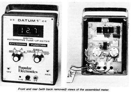 Tune-Up Tips.
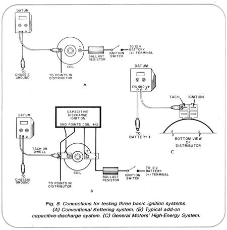
 Although dwell angle is independent of engine
rpm, the display will normally fluctuate slightly. Large, rapid
readout fluctuations suggest that the points are bouncing.
Increasing the tension on the point spring should alleviate this
problem. Large gradual fluctuations in the display may indicate a
worn and wobbling distributor shaft.
Although dwell angle is independent of engine
rpm, the display will normally fluctuate slightly. Large, rapid
readout fluctuations suggest that the points are bouncing.
Increasing the tension on the point spring should alleviate this
problem. Large gradual fluctuations in the display may indicate a
worn and wobbling distributor shaft.Copyright by Bill Bytheway, K7TTY February 2012