|
Diode Switching Circuits
The switching circuit in Fig. 8 steers a
single audio signal to a choice of two outputs. When a positive
voltage is applied to the anode of either diode, through R2 or R3,
its internal resistance goes from near infinity as an open switch,
to a low of a few ohms when closed. If both s
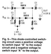
The diode-switching circuit in Fig. 9 uses a positive voltage to switch input “B” to the output circuit and a negative voltage to switch input “A” to the output. All three of the diode switching circuits can handle audio levels up to 2- volts peak-to-peak, and operate with a bias voltage of 9 to 16.
|
 Diodes
are useful for more duties than just changing AC to DC. The circuit
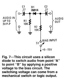
in Fig. 7 uses a silicon diode to switch audio from point “A” to
point “B” by applying a positive voltage to the bias circuit. The
switching bias voltage can come from a mechanical switch or any
logic output.
Diodes
are useful for more duties than just changing AC to DC. The circuit
in Fig. 7 uses a silicon diode to switch audio from point “A” to
point “B” by applying a positive voltage to the bias circuit. The
switching bias voltage can come from a mechanical switch or any
logic output.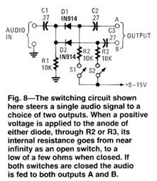 witches
are closed the audio will be switched to both outputs A and B.
witches
are closed the audio will be switched to both outputs A and B.
Copyright by Bill Bytheway, K7TTY February 2012